

In the debate about Steel or Aluminum for beams of trailer frames and gantry cranes, there is one big piece we hear less about. An important part of the equation, for sure, is the property of Elasticity . . . . What? It has to do with what we often call stiffness of a material. And, stiffness is pretty important for structures like Cranes and Trailer Frames.
We discuss a lot about Weight, Corrosion, Strength and other comparisons in Steel vs. Aluminum Part 1. We recommend you read that now if you haven’t already. Now, in this article, we’ll focus on the engineering concept of Elasticity since it is a big factor in choosing one material over the other. Interestingly, it becomes ever more important as beams get longer.
Engineering Concepts
The engineering term is “Modulus of Elasticity“, and it relates to how much a beam will deflect under a given load. It is a property of the material — Aluminum, Steel, Titanium, Plastic, Wood — they all have a different “Elastic” property.
In discussions of Strength and Stiffness, another related engineering principle is often referred to as the “I”, or “Area Moment of Inertia“. This has to do with the size and cross sectional area of the beam. Oversimplified, it’s the amount of material, it’s distribution in the beam cross section, and the distance from the furthest stressed portions of the beam section. Follow the above links for more complete descriptions.
In essence, these 2 principles combine in a beam, any beam, to define how “Stiff” it is. This is not “Strength” — though they are often related. It is not the beam shape, though that has a lot to do with it.
Let’s look at an example using a simple Gantry Crane top beam, and let’s look at it through the lens of Finite Element Analysis (FEA). We’ll use this fun engineering tool to make our comparison of Steel vs Aluminum because it gives some great visual perspectives. (As a side note, to see what happens when a crane does collapse, check out Safety with a Crane, and the bigger one — Gantry Crane Failure Modes.)
Insight From Engineering Tools
To start, we build two cranes. Well, not actual cranes, but build them in CAD. One crane has a Steel top beam, and one has an Aluminum top beam. All the legs are the same, in steel, so we can easily see the differences of just the top beam. We’ll then load both of the gantry beams with 2500 lbs hanging from the center. This image below shows how cranes and loading are setup.

FEA Setup
The legs each constrain at the bottom. For simplicity we assume they are fixed, knowing in reality that’s not exactly true, but for the simple comparative analysis it will do. We also bond (weld) the legs to the top beam, which again, is not exactly true, but good enough for the insight we are seeking.
For this first test, both top beams are 5″ I-Beams. The only difference is one beam is Steel, and one is Aluminum.
FEA – Finite Element Analysis – is an engineering tool that lets us look virtually at what happens when we apply a load to an object. The colors, like in the image below, represent stresses in the beam. Blue and Green in this example are “safe”. Yellow is “caution”, and Red is “scary”. It works for both steel and aluminum. The deflection in the image is drastically exaggerated so we can visually see what is happening. (For an actual crane you would not see this kind of bending of the beams.)
For our load, the two gantry cranes look something like this.

5″ I-Beams
This image shows a deformation scale of exaggerated 30X. That means what you see is 30 times more deflection than in reality. We use this kind of exaggeration to get a better visual picture of what is actually happening. It’s easier to see, and the exaggeration is the same for both beams, so we can get a feel for the difference of Steel vs Aluminum.
The actual deflection of the Steel beam is just a little less than 0.2″. (Take these numbers with a grain of salt because of the setup assumptions). Deflection of the Aluminum beam is almost 0.5″. Note that stress is very similar except for the hot spots around the leg connection. Those spots really come from the greater deflection, which the legs try to resist. Of course you can’t really weld steel legs to an aluminum top beam. Yet, this is an interesting symptom of the connection when a deflecting beam transfers some deflection into the connecting members. Keep this in mind for later.
From a practical standpoint, if the top beam of a gantry crane deflects 0.5″, it could be hard to move the load along the beam because you’d actually be pulling it up a comparatively steep slope. 2500 pounds is a significant weight. Yes, the deflection moves with the load, and it is a compensation, but it is not a desirable situation.
6″ Aluminum I-Beam
In an attempt to reduce deflection and to strengthen the joints, let’s replace the 5″ aluminum beam with a 6″ aluminum beam. This is the result.

In the FEA image we can see that deflection is definitely less. Now it’s about 0.3″ for the aluminum beam, which is good, yet still more than the Steel I-Beam. Stress is also down, which is good. And, we see the hot spots reduce because the beam deflection is less. All of these are moves in the right direction.
 The change we see in beam deflection is due to the greater “I”, or “Area Moment of Inertia”. Aluminum material is still the same, only the size has changed. While the beam has a taller section from 5″ to 6″, that is only part of it. The 6″ I-Beam also has more cross section area.
At this point we can decide if the 0.3″ deflection is acceptable. In some practical cases it may be, but for this analysis, since the deflection of the aluminum beam is still more than the steel, let’s change the top aluminum beam again. We’ll do this to illustrate the elasticity difference in comparing the materials — Steel or Aluminum for the beam.
8″ Aluminum I-Beam
For I-Beams, the next standard size up is 8″, so that is the next step for our analysis. Please note that we are still comparing to the 5″ Steel I-Beam.
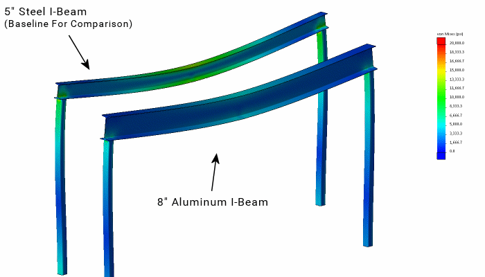
In this image, we can easily see the 8″ Aluminum I-Beam further reduces both deflection and stress in the joints. The hot spots are gone, and this time deflection is just below our 0.2″ steel beam target. We have success in our comparison.
Of course, the new 8″ aluminum I-Beam is much taller, and it also has more cross section area. Because we use standard size material, the 8″ I-Beam is also quite a bit wider — 4″ wide vs 3″ wide. All these things make a difference that is not readily apparent in the description of 5″ or 8″ beams.
Note also that the stress in the 8″ I-Beam is less, quite a bit less. What that really means is we have a lot more material than we need from a strength standpoint in order to achieve the deflection goal. Remember our objective is to compare steel or aluminum for the crane, yet it is also true for a trailer frame.
Deflection Comparison: Steel vs Aluminum Beam
So what have we learned? This is a simple example where deflection is the driving factor in a design rather than stress. Even the first example had acceptable strength as indicated by the stress (if we strengthen the corners with proper gussets). Really, for longer beams, deflection is usually more the concern. Can you imagine your tiny house if the trailer deflected an inch in the front and back? (And even more with the dynamics when driving over bumps?) You’d have some big house cracks to deal with.
This is not to say Aluminum is a bad material for crane beams or trailer frames. Not at all. I actually love aluminum. The above analysis just highlights one of the caveats for comparing a Steel or Aluminum beam. And, it highlights some of the differences if we decide to build in aluminum versus steel. As we have had discussions about aluminum trailers, this is one aspect that many people don’t think about, but it’s important. As we see, there is compensation, but it’s not as clear as one might first think.
Selecting material for a project is always a challenge and a balance of strength, loading conditions, weight and appropriate safety factors. This is especially true when customizing plans like a gantry crane in the above example. We encourage customization, informed customizing, with care as illustrated.
Choosing — Steel or Aluminum
There are many advantages to using aluminum as pointed out in our Aluminum vs Steel Part 1 article. There are also some disadvantages including the extra deflection we see in the example above. This simple study with a gantry crane beam makes it easy to see and understand. It is also easy to superimpose the concepts onto other applications like trailer design.
If we think about the main beam of a trailer frame for instance, if deflection is important, then the main beams will need to be bigger (taller) for the aluminum trailer. That may make the deck height go up some too, which may be fine, or maybe not. Also, keep in mind that this effect height change requirement becomes greater as the beams become ever longer (as for a longer trailer).
We have not changed a thing in the debate over Steel vs Aluminum. More importantly, that’s not what we set out to do — because there is little point to debating. Both are great materials. Both have good advantages, and both have drawbacks for any given application. Our purpose is simply to broaden perspective and give one more perspective for making decisions. The choice of material should be the best one for the job.
Even with all the discussion in this and the previous article, there is more. There is always more. For another view about steel or aluminum for trailers, try this article: Are Aluminum Trailers Good or Bad? And/Or, see the answer to one of our frequent questions about building trailers: Can I build your trailer plans in Aluminum?
Enjoy.


Comments