

This is a Customer Story about a crack in a trailer frame. Finding these can be really scary, but finding them at this stage is a whole lot better than finding them after a catastrophic failure.
First, I have to compliment this owner for taking the time to look at things while checking the hubs. Seriously, not many people will take a minute to look things over closely as he did.
Usually when we find out about cracks in the frame, it is after a catastrophic failure. They are picking up pieces. So again, good job being aware.
Finding the Frame Crack
In the customer’s words . . . “I have a 2014 28′ Continental Cargo Enclosed trailer with Tandem torsion axles (I know, I read your articles how this is not a good setup). Anyway, I was checking the hubs on the trailer last weekend and noticed a crack running along the bottom flange of the main beam behind the back axle where the bracket is welded for the axle.”

“The Main beam is back to back sistered c channels. The crack only appears to be running through the bottom flange at this time. The brackets were welded to the beam longitudinally on the sides only. The crack to me appears to have initiated from the end of the welds on the side. The brackets had no buffer piece between the beam and the bracket.”
Here are some close-up images of the area. I had to stare at these for a little bit to get the perspective.


I have labeled a few things in the images here so they are easier to see. Hopefully that helps some.
Explanation of the Images
Looking at the first photo with the 2 axles exposed, you can see the torsion axle brackets under the main frame beams. They actually sit slightly proud of the C-Channel (outboard) as you can see in this view.
The torsion axle brackets mount to short pieces of steel angle which serve as the connection bolting points for the Torsion Axles. The Angle bars weld to the Channel flange via 2 parallel welds.
In the top view, it is a little harder to see the weld because of all the dust and dirt. (Yeah, it looks like rust, but I think it’s just reddish dust because you can clearly see where it is wiped away to show the crack.)
The frame crack starts right at the end of the weld – right at the end of the angle iron mounting piece. It’s hard to see from the bottom side because it extends just under the edge of the angle bar.
I think angle bar is a good choice for mounting the torsion brackets, but the length of this piece is much too short, and is a contributor to the frame crack.
Crack Causes
The crack in the trailer frame has 3 main causes:
- First, the axle mount is roughly the same size as the axle bracket. That doesn’t compensate for the high moment stresses from the torsion axle.
- Second, there is an abrupt change in metal cross section (a transition) at the edge of the angle bar. (As pointed in the image, right where the frame crack starts.)
- Third, the weld goes right to the edge of the transition point (where the crack starts, on the top side of the axle mount, along the edge of the flange). That means heat of the welding affects strength of the beam right at the point of highest stress.
- The tandem torsion axles create extra high loads at times due to momentary overloads.
- Perhaps a secondary effect: The angle bars for mounting the axles are only on the flanges of the C-Channel. That means the flanges will flex slightly with the trailer loads. In combination with the items above, this deflection puts even more stress at the key point.
That’s a bad combination. Welding affects the metal, no matter what you do, so make sure the welds are supported beyond the stress risers. Make sure to support the loading all along.
For this case, if the manufacturer had just made the axle mounts longer, there would be no issue. If they had stopped the weld a few inches from the end, the crack probably would not have started. (I will say it’s nice they did not weld across the flange from the bottom. That’s certainly good.)
This kind of failure is totally preventable. IMHO, this is just cheap construction.
Avoid This Kind Of Frame Crack
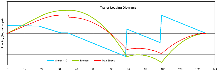
As the customer noted in the problem description, the best way to avoid this kind of thing is to have a buffer piece span significantly in front and behind the axles mounting. Here is the engineering analysis showing the added stresses applied by a torsion axle. Applying it to this case, we can see the highest torsion axle applied stresses are at the top of the beam, but the bottom is also affected. And highest right at the edges of the bracket.
Then, this article which explains why we strongly recommend the buffer piece between the axle and the trailer frame. It shows the principles using leaf springs. Yet, stresses are higher for torsions, so the problem is more severe. Honestly, this story highlights why we make the recommendation. It’s not just a goofy idea from a looney engineer.
Finally, don’t use torsion axles (or any other kind of independent suspension) in tandem (or in triple). Here is the engineering. These configurations create momentary overloads, and even if the axle can take it, often other parts cannot. While we can’t prove it here, I believe the tandem torsions are part of this frame crack.
Anyway, it’s a little late for this trailer without a huge tear-up. Fortunately, because of the construction, we can avoid a complete tear-up – if they are willing to live with the tandem torsion problem.
The Fix
Obviously, this is a unique situation that is not applicable everywhere. Yet, for education and something to think about, here is our recommendation to fix it.
The idea with the buffer piece is to spread the load to the main frame beams. We can do that by putting something under the beam as noted in the article. Or, in this case, because the flange of the main beam is accessible, we can add material on the inside of the flange. The idea is to strengthen the area sufficient that there are no significant stress risers. Also we want to take the load off the flange, and transfer it to the web (vertical portion) of the beam.
See the image, then follow these steps.

Step 1
Wire wheel the frame, as much as is practical, especially around the crack. Also, everywhere the new (green) part will attach.
Step 2
Grind out the frame crack as much as practical, but only from the top side (where the crack is visible in the image above). Don’t worry too much, but we want to remove metal about half way through the flange. It will be a little tough since it’s near the beam web. Just do what you can.
Step 3
Weld fill the frame crack, just on the top side, then grind it off flat. (When you are all done with the fix, the bottom of the trailer where the axles mount will still look the same. – Unless you also want to give it some paint.
Step 4
Choose the new (green in the image above) support bar. This shows square tube, but rectangle will work. Wall should be at least as thick as the channel thickness, or more. It should be a little wider than the flange, but not beyond the edge of the angles used for mounting the axles.
Cut the new support bar to length. Make it extend 18″ to 24″ beyond the axles, both in front and in back. Weld a cap on the ends so water can’t get inside.
Step 5
Paint the trailer main beam and the new support bar with a high-temperature primer. Rustoleum has a commercial gray primer that’s good to 2000° F. Or use black barbecue paint. Something to keep it from rusting between the pieces.
Step 6
Place the new support bar in place. Clamp it to the flange. It may or may not seat nicely to both the flange and the web of the main frame beam, but if you must give a little space do it on the vertical web. You can bridge the vertical gap with weld.
Step 7
Weld the new support bar in place. Stitch weld, 1″ every 6″ or so. Does not have to be exact. Weld to both the flange and the vertical web, but NOT across the flange. Also, Do Not Weld within 3″ of the bar ends.
Step 8
Paint everything, then seal the areas of contact with a good outdoor silicone or RTV to keep water out. (Some people use Bondo. I don’t normally like that because it can crack.)
Step 9
Of course, make the same fix on both sides of the trailer. The other side may not be broken, yet, but add the new bar so it won’t.
That’s it. The crack fix is not too extensive, and should repair the frame for more great travels. Thank you for allowing us to share this project with all the readers at Mechanical Elements.


Comments