

I love seeing failures. Not that anyone wants things to fail, of course, we always try to make things that last. However, when a failure pops up, I love to look it over and understand the “how” and the “why”. It is an excellent opportunity for learning, and I love to learn. In this case this failure highlights welding strength and what happens in the periphery around the weld. Let’s see what we can learn.
 This example is one worth sharing because it is a real life illustration of the theory we talk about.
This part started life as a mounted trailer drawbar receiver. This is a typical 2″ receiver to accept a trailer hitch drawbar. It is just like the ones on the back of a car or truck, but with a mounting plate. The plate (once flat) welds to the receiver, then bolts onto a test machine.
While we don’t know the exact dates, it seems to have functioned perfect for something like 15 years. Then the duty changed a little in more recent times. Now, as you can see in the images, at some point, something went horribly wrong.
Forensic Evaluation
It is like looking at a crime scene and trying to pull together the facts of what went down. We see broken and twisted bits of what was once a single flat piece of steel. We see heat staining as witness marks of the welding (many years ago), and witness marks from the bolts that held it. That is the start.
Looking a little closer we also see that some of the “tearing” or fracturing of the material happened fast, and some happened slow. How do we know? In metallurgy a fast break in steel leaves a granular look, often dull in appearance, but clean. It looks kind of like very fine sand.

On the other hand, a slow break (like fatigue failure) usually has some shiny areas because the inner portions of the crack fret against each other making the surfaces a little more shiny and a little less grainy. It may also look a little dirty since it takes some time for a fatigue failure to occur.

I am not an expert, so I won’t elaborate too much. Yet, it is fascinating nonetheless to examine the members and see where the cracks probably started, and to see how they likely progressed. Super interesting.
Also, the other things that tried to resist the failure. The bolts, in this case, we can see where they rested for years, and how they resisted when the material tore away. Note the 2 elongate from round.
What Happened?
First, we don’t really know for sure. This is the hypothesis.
It appears a crack started near the end of one weld. Progression was likely slow, along the edge of the weld to the periphery of the plate. Once the initial full fracture happened, the rest probably went pretty fast. There is likely some fatigue near the welds on the other side too, because as one side moves a little, the other side will also. With one side mostly broken, a lot more stress occurs on the on the remaining side, which makes the break happen faster. Even with the added stress, the failure appears to start near the edges of the welds.
At some point, the one side probably failed completely, letting the drawbar “flap” with the other side, and was likely just a few cycles until catastrophic failure. The side with so many little pieces an the elongated holes is probably the last side to fail.
This mangled metal took some serious force as it tore. Impressive. To me, this is pretty impressive that it tore in multiple directions all at once.
Welding Changes Material Strength
We have discussed welding results in previous articles like this one about welding brackets on a trailer frame and this one about building with aluminum. It is one thing to talk about how welding affects strength of the base material, and quite another to see the outcome after stress.
You might look at this failure example and say “yes, but the unwelded areas also broke”. And, you are right.
You might also look and say “the weld didn’t break”. Again, you are right.
While these are both good observations, it appears the fracture started in the fringes by the welds. As we note in the previous articles, the primary area of concern is the parent material right near the weld. Not the weld itself. (Assuming, of course, that the skill of the person welding is sufficient for the task.)
A weld increases thickness of material locally, so it is stronger. Unfortunately, the area right around the weld also experiences the extreme heat, but it does not get the benefit of added material for strength. Weld stress is induced in the parent material at a boundary of “hot” and “cool”. We see that in this failure sample. The material did not start out weak. No, the welding changed the strength properties locally, making it more susceptible to fatigue, cracks and breaking.
More Welding Strength / Failure Examples
The example above is steel, and we see even with steel the need for careful design for welding. For further reading, here is an example of an Aluminum trailer tongue break. Oh, and the follow-on article about design to prevent failure using the aluminum trailer example.
The full discussion about how welding changes things goes deep into material science and includes discussions of atomic structure as well as alloying elements. Metals will take on different properties depending on how they are heated and cooled.
In the case above, the worst bit is the area that did not heat completely, then likely cooled too fast since it was near metal that did not heat as much. That boundary at the edge of weld makes materials particularly susceptible to fatigue and to failure – unless proper care is given.
The Take-Aways
In every experience, it is good to think about what we can learn. Here is a sample that felt good, and for 15 years it performed well. The conditions changed a little in the machine settings, and that caused (or at least finished) the failure. In this case, nothing of consequence was damaged, but we don’t want a failure again. So, what can we learn?
- For high stress elements, think about welds that are in a line and the possibility of propagating cracks along the weld lines.
- We like good weld penetration as that makes it strong. On the other hand, the heat stains here remind us that welding creates a lot of heat and that has effects down the road. When we have high through heat like this, we need to think about potential strength changes because of the welding.
- Stitch welds are intended to spread heat distress so the material strength is not as affected by the welding. Hard to say here how much that helped, yet judging from the marks, it did help.
- 15 years is a long time in service, and that is a lot of abuse to take. Goes to show that even when it works for a while does not mean it is totally invincible.
- I think the base plate material was a little too thin for the application overall. This is a case of being right on the edge of good enough / strong enough.
- The small change in service was a little more than the bracket could hold. It was designed for one application, which it did fine, but the change was too much. We need to watch how we make changes, then make sure the parts are up for it.
- As we plan for other projects, it makes a lot of sense to evaluate the importance. In this case nothing was really hurt, but a failure welding brackets for Trailer Safety Chains, for example, might be catastrophic. This serves as a good reminder about the importance of what we are welding.
Professionally, just as well as in DIY, we always do the best job possible – as I am sure you do also. And yet, there are always things to learn and improve. Keep your eyes out for opportunities!
Solution – Welding Again For Strength
 The example here illustrates the efficacy of a concepts we teach. Welding does change the material, so moving the welds from the direct stress points is a big way to help. Another way is to use a buffer (thicker) material directly by the weld, and to support the weld area. Look again at our recommendations with welding brackets on a trailer frame. You will see the same fundamentals with this solution.
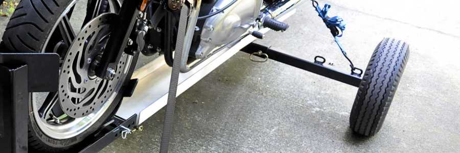
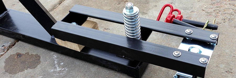
How about a few photos of the revised receiver plate? Now, the main welds are no longer in line (on the same piece of metal), and the loads are through thicker material. The receiver welds are now at the ends as well as on the sides. Most of the welds are now on the thicker members, and they share loads all the way from the receiver to the bolts. The plate material will still cover as needed, and it combines the loading, but it is not the main weld member any longer.

In 15 years we shall see if this works or not, but I personally think this is a much stronger design. Could I have just used a thicker piece of material for the plate? Sure. That would also work, though it would be heavier. I have to admit, however, I didn’t have a thicker piece that wide, and he needed the fix right away. This idea works as a good way to optimize the design for weight a little too. Having the welds on separate pieces certainly eliminates the possibility of propagating a crack all along and all through as before.
Wrapping It Up
Hopefully there is something here to take away as we highlight an example of strength changes in the material from welding. There is nothing wrong with welding, as long as we stay within the parameters of success with it.
As I see more and more of such failures, I emphasize the need to really think about our welding. In other articles, and in places in the trailer plans, I say “Do Not Weld” here or there. Things like this component failure emphasize why.
Now in fairness, this 1/8″ metal plate was not up for the more severe job. We considered that before putting it into service, but decided to try it. Now we (and you) know better. Good luck.
Updates:
After a year in service, still at the higher level, the revised part is working fine. Everything indicates success.
– Now 3 years later, still running well.
Thank you for joining us for a few minutes to talk about welding strength. Enjoy your day.
We appreciate your kind contributions.
Thank You.


Comments